


Aerodynamics is an interesting and one of the most challenging fields of science and engineering. You can even win $1 million if you can contribute to the understanding of the underlying math. Aerodynamics is generally described with the Navier-Stokes-Equations, but even the fastest super computer in the world is not capable to solve these equations directly for a reasonable engineering problem. Instead, simplifications must be introduced, which are rather significant, to have a chance of computing a solution in a reasonable time with reasonable computer hardware. This is also a reason why wind tunnel tests still have to be performed until one can be sure if the computed result is really correct. In this blog post we give a few insights on Kitekraft’s approach to solve this aerodynamics challenge. As a spoiler, we have found an accurate and extremely fast solvable 3D aerodynamics model, which we use for design, optimization, real-time control, and software verification, and we think about making it available to everyone (link to waiting list below).
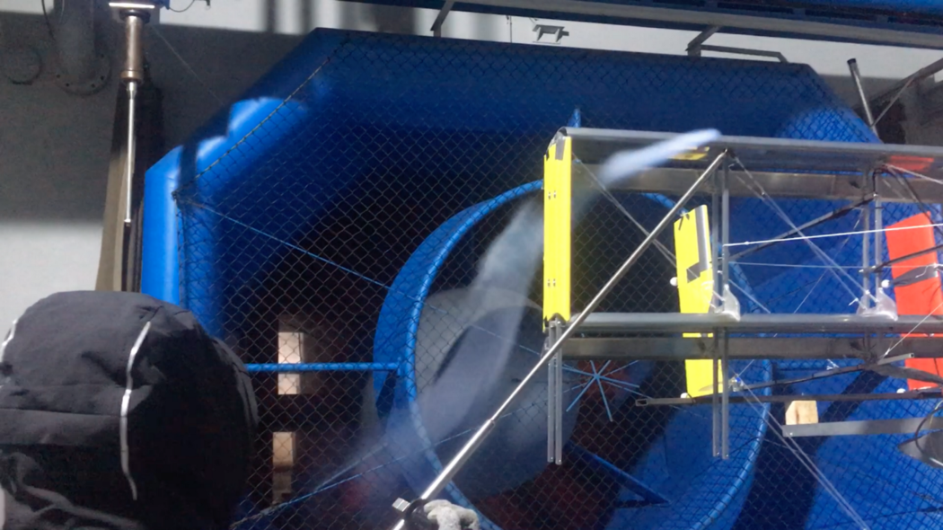
In the video below you can see Kitekraft engineers preparing a kite for wind tunnel testing.
How We Optimized Our Elevator Airfoil
One of the many simplifications of the Navier-Stokes-Equations is implemented in the software XFOIL. It is developed by Prof. Drela from Massachusetts Institute of Technology (MIT), is open source, and can be downloaded here. XFOIL can compute solutions extremely fast in a matter of milliseconds to seconds, but it computes only a 2D flow which is typical around airfoils and works only as long as no large separation bubbles or other strongly non-linear effects occur anywhere. Despite those limitations, the software is quite popular in the industry and academics, because it covers flow regimes which are typical for an aircraft.
Below you can see a video recording of Kitekraft’s elevator optimization: GNU Octave sets up the optimization problem and cost function. The cost function calls XFOIL for every candidate airfoil and computes the cost. The CMA-ES optimization algorithm alters the geometry of the airfoil in a way, such that the cost gets smaller and smaller and thus the airfoil becomes more and more optimal.
At Kitekraft we used XFOIL in combination with the optimization algorithm CMA-ES and the mathematics tool GNU Octave to optimize the airfoil of our kite’s elevator. Above is a video showing how these tools are used to execute the optimization and the image below shows how the optimizer iterated to the optimal airfoil. The elevator of our kite is a fully rotatable horizontal stabilizer mounted to the tail (tail-plane/empennage). It helps to stabilize the pitch angle during hovering, for which it is normally rotated about 90° (i.e., trailing edge of elevator wing up/nose of that wing down), while during figure eight-flight it helps to stabilize the angle of attack. The total angle it must be able to rotate is about -30° to 110°. A small electric motor is attached to it, to rotate the elevator to the exact angle according to the flight controller’s command every 25 milliseconds. This airfoil must generate a decent amount of lift while having a small as possible amount of drag. Another very important goal for our optimized elevator airfoil is to have a minimal as possible aerodynamic moment, because this enables to use a very small and light electric motor. One has to know here, that the moment of an airfoil is generally a function of its angle of attack and airspeed. While for a certain angle of attack and airspeed one can find an axis of rotation, which is exposed to no moment, but once the angle of attack changes, the moment can still change in general. Because the airfoil must be capable to generate positive and negative lift, the airfoil should be symmetrical. This also has the benefit, that the geometry of the airfoil has few degrees of freedom for an optimizer to look for.
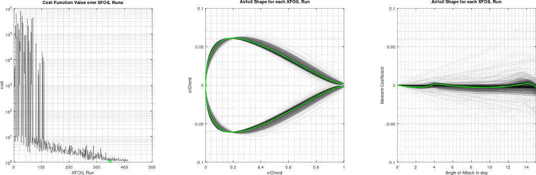
With all these specifications, we set up the optimization of the airfoil to minimize the moment coefficient for all angles of attack from 0° to 15°, i.e., the cost function is set to be the absolute sum of moment coefficients of all those angles of attack. It should be noted, that we do not state anything about the lift and drag coefficients in the cost function, instead we check after the optimization has finished if the airfoil ended up with decent lift and drag coefficients. The advantage of this approach is that the optimization formulation is simple and, in particular, single-objective instead of multi-objective. The airfoil is described with a spline and the optimizer can change some of the spline points, which also helps to test only meaningful airfoil shapes. The optimizer can also choose the position of the shaft, i.e., the position of the rotation axis.
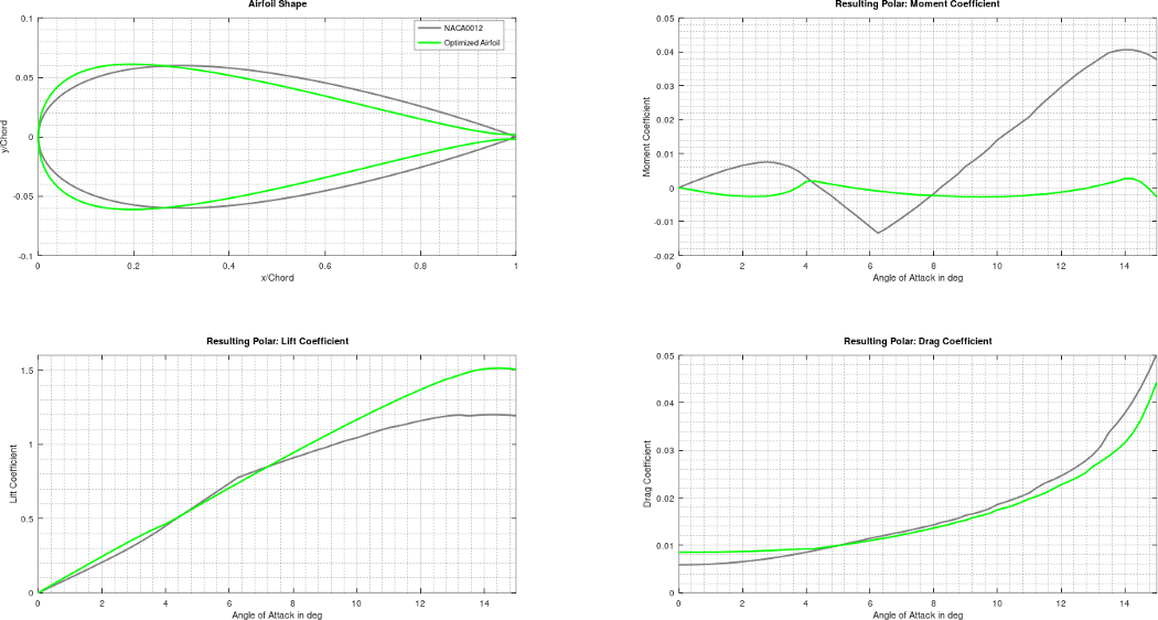
The image above compares the shape and aerodynamic coefficients of the standard NACA0012 airfoil in gray with the optimized elevator airfoil in green. It is visible that the optimized airfoil has a reflex-like shape characteristics, which is somewhat expected from the goal we wanted to achieve. The lift and drag coefficients above ~5° angle of attack are significantly better than that of the NACA0012 airfoil, with the maximum lift coefficient 25% higher, even-though such a goal was not explicitly stated in the cost function. The moment coefficient is pretty excellent as well, very close to zero over the entire investigated angle of attack range. Specifically, the maximum moment coefficient of the optimized airfoil is ~16 times smaller than that of NACA0012. We also measured the aerodynamic characteristic of the elevator wing in the wind tunnel, which was in good agreement with the prediction based on XFOIL.
A similar approach was used for the optimization of the other airfoils of the kite. However, this is a much more complex endeavor, as the main wings have to be high-lift airfoils with at least two elements. Some details on how this can be approached is outlined in the scientific paper here (free preprint available here) which also details why high-lift airfoils are optimal for flying wind turbines/power generating kites.
From 2D to 3D, and What About the Rotors?
So far, to solve the Navier-Stokes-Equations, we have made the big simplification of looking only at 2D flows around airfoils. This is essentially only valid for wings with infinite span. For actual 3D flows around a wing or generally around an aircraft (or any object), this is almost always too inaccurate. The photograph below visualizes one effect that is not covered by a 2D flow: vortices that are forming at the wing tips. These vortices are the cause for a lower lift coefficient at a given angle of attack compared to the 2D results as well as a significantly higher drag coefficient. The vortices are stronger for low-aspect ratio wings or high-lift coefficients, the latter is what we have for our kite. The vortices also influence the flow that is seen by the tail-plane. Even more, there may be rotors operated in propeller mode or wind turbine mode in front of wings, and thus, the wings may see downwash of the rotors, or vice versa, rotors may see aerodynamic effects caused by the wings.
There is a number of possibilities to address this in an aerodynamics model, e.g., the vortex lattice method (also known as a panel method) or finite volume method (commonly referred to as CFD or Computational Fluid Dynamics), which both have many “flavors”, e.g., many approaches on how to simplify the Navier-Stokes-Equations by using different turbulence models. The general rule is: the higher the accuracy one wants to achieve, the more computational resources are required.
The panel methods are usually valid for low angles of attack only. This is unusable for our power generating kite application. During hovering, transitioning from hover to figure-eight flight, and transitioning back from figure-eight flight to hover, the angle of attack is anywhere between approximately –10° to +120°. — This is also the reason why a simple linearized model, which is usually used in flight simulators, is not sufficient for us.
CFD computations do not have this limitation. So one can come up with the idea to use a super computer and compute everything one needs. For real-time flight simulations, this would mean to generate an offline-computed large lookup table having the x-y-z aerodynamic forces and x-y-z aerodynamic moments as function of flow conditions (6 variables: airflow speed, angle of attack, angle of sideslip, x-y-z-angular rates), control surface deflections (for our kite currently 7 variables: 6 flaperons, 1 elevator), and rotor speeds (8 variables, because of 8 rotors on our kite). However, it takes several hours to days to compute a 3D CFD just for a single flow condition and kite configuration. Assuming we need just 10 values for each of the variables listed above, we would need to execute: [10 values per variable] to the power of [6 + 7 + 8 variables] = 10²¹ CFDs. Assuming optimistically that one CFD takes just 1 hour, this would take 100 million billion years to complete — which is obviously too long. Now, let us assume, you found that, say, increasing spacing between the rotors increases the aerodynamic efficiency: you have to compute everything allover again and wait another 100 million billion years. For sure, one can find that there are symmetries and the number of simulation runs may be reducible, but not significantly enough to have the computation completed in a practical time frame of days or weeks. Interestingly, the Makani engineers ran into the same problem and wished to have a solution (if you do not know Makani, you can have a look in our previous blog post).
The next video shows a demo of the capabilities of the nonlinear vortex lattice blade element aerodynamics model developed at Kitekraft and used for the kite design, kite dimensioning, kite optimization, kite real-time simulation, kite real-time control, and flight control software verification including finding and verifying the handling of corner cases with Monte-Carlo batch simulation runs. (Tip: watch in full-screen and maximum resolution.)
At Kitekraft, we found a solution! The video above shows a demo. We combined the vortex lattice method with the nonlinear 2D airfoil polars (i.e. lift coefficient, drag coefficient and moment coefficient as function of angle of attack and flap deflection), which are lookup-tables and may be computed relatively simply and quickly with XFOIL, any other CFD, or measured in a wind tunnel. This aerodynamics model is also called nonlinear vortex lattice blade element model. Specifically, each wing is subdivided span-wise in wing elements, each wing element has a vortex horseshoe and a 2D airfoil polar. The vortex strength of each wing element is calculated by solving the nonlinear coupled aerodynamics equations, such that the lift calculated with the Kutta-Joukowski theorem is equal to the lift calculated with the 2D airfoil polar, which depends on the effective angle of attack and thus depends on every vortex horseshoe. Rotors (propellers/wind turbines) are added with additional induced velocities in the flow at respective positions.
This modeling approach itself is not really new, but it is new that our solver algorithm can be executed extremely fast — much faster than real-time — , is guaranteed to never diverge, and usually finds the solution with a few iteration steps only. This enables not only real-time and faster than real-time execution of the aerodynamics model. It also enables to compute the optimal control surface deflections in real-time on the kite, to meet the desired moments demanded by the PID attitude controllers. So, our aerodynamics model is executed thousands of times per second within the control algorithm of the kite controller during flight. This approach specifically enables that no linearized aerodynamics models and accordingly no linearization-based controllers need to be used, which are valid only in a very limited range (this is the conventional solution in flight simulators and autopilots). In contrast, our aerodynamics model in particular is also valid in non-linear regions including actuator saturations, post-stall, and hovering when the angle of attack is ~90°. Moreover, our model covers the various rotor states with its respective induced velocities both during propeller mode and wind turbine mode. Another highly valuable application of this model is its use in Monte-Carlo batch simulations for our kite design verification and flight control software verification: hundreds to thousands of complete flights from launching to landing are simulated with stochastically varied parameters, wind conditions, and fault conditions to find software bugs, to find corner cases, and to verify the flight controller’s handling of all those flight situations and corner cases. This particularly enables many and fast learnings and iterations just from the software and simulations, instead of costly and time-consuming flight tests.
We validated the model in wind tunnel measurements and flight tests: The wind tunnel measurements are in good agreement with the model predictions, and the data of the particularly challenging transition phase from hover to figure-eight flight and back is almost indistinguishable between measurement and simulation. A video of such a flight test is shown below.
An finally, a video of a flight test of our kite in all phases, including the aerodynamically challenging transitions from hover to figure-eight flight and back.
Those capabilities required for our kite and the limitations of traditional/existing approaches were the reasons we have developed this aerodynamics model and could not use any existing code or tool.
Making this Available for Everyone
We do not intend to keep these capabilities just for ourselves. Our mission at Kitekraft is to help de-carbonizing the global economy. Solutions besides flying wind turbines are required and may benefit from our aerodynamics model, e.g., eVTOL air taxis or general electric/low-carbon aviation and much more. We want to find out! — We are currently evaluating if and how we should make this available. If you are interested in using our aerodynamics model for your use case (research, commercial, other), you can sign up on our waiting list. During signing up, you are also invited to give more details on how you would be using it and what features you would like to have. Click here to get onto our waiting list. If we publish this software, we’ll notify everyone on the waiting list and we will also communicate this via our newsletter and social media channels.


