


In July 2023, Kitekraft's engineering team took our current development platform and 1:4 scale product to the wind tunnel to investigate aerodynamic aspects of its flying wind turbine design: Hovering in high winds and the performance of in-house designed rotors, which where manufactured form carbon fiber reinforced plastic (CFRP). Both investigations could be completed with positive results, as described in the following.
At first, insights into the hover tests will be given.
While the operational mode of Kitekraft's flying wind turbine design has already been proven through wind tunnel tests and actual flights (such as this one), extensive evaluation of the hover mode in high winds was not yet possible. This mode of operation is crucial for take-off and landing in high winds.
To gain further insight into this behavior two test setups were investigated in the wind tunnel, one of them shown in the figure below. On the left side, the setup for measuring the aerodynamic coefficients of the kite's airframe is shown. For these measurements, the tail and docking lances were removed, and the remaining airframe was mounted on a measuring shaft. This measuring shaft includes a gauge for force and moment analysis and can be pitched and yawed with respect to the airflow of the wind tunnel (flowing from right to left). Different angular sweeps were recorded and the resulting aerodynamic coefficients will be used to advance the aerodynamic real-time model which helps navigate the kite in midair (read more about it here).
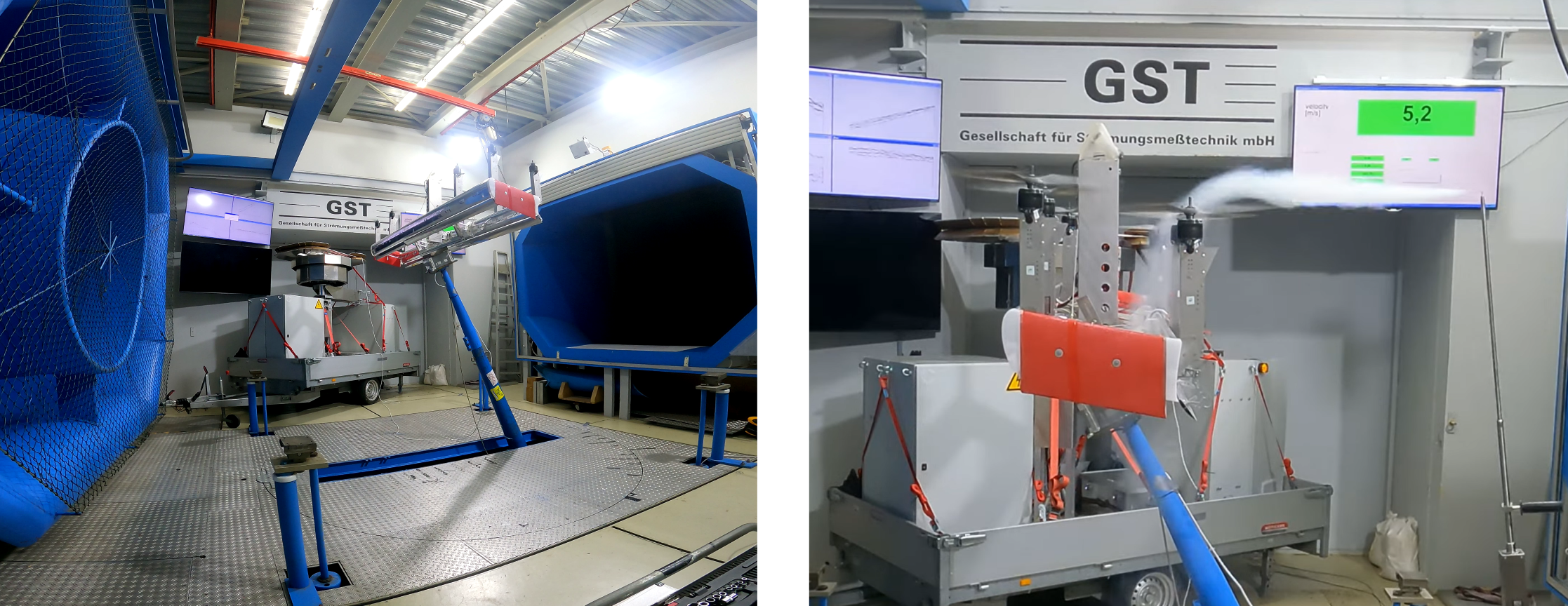
Besides quantitative measurements, a smog probe was used to qualitatively analyze the flow behavior around the kite. This is shown in the right image of the above figure, where a flow of 5.2m/s was present, as indicated in the green box in the upper right corner. It can be seen, that the fog is pushed down by the rotors, over the wings and their control surfaces, the flaps, which can be set to deflect the airflow in different angles. This effect is used during hover flight to steer the kite in yaw direction, but control authority is only given when flow is pushed over these control surfaces.
With more wind, the fog is pushed more downstream (to the left side of the picture), which might lead to compromised control authority. This configuration was tested with wind speed of up to 20m/s and it could be shown that the fog was still pushed over the flaps of the upper wing, meaning the system still has enough control authority to navigate in a controlled manner.
Biplane design suited for hovering in high wind.
The second test setup with the kite can be seen in the image below. The measurement shaft was removed and the kite maintained hover position by using the onboard rotors, just as it would do during take-off or landing. Running to the right edge of the image, a rope which emulated the tether (aka mechanical attachment to the ground station) can be seen. Besides that, several safety ropes were attached to the kite, to avoid damage to the kite in case of an emergency shutdown. Instead of attaching the actual tail, an emulator was attached this time to it to keep the dynamic properties of the kite similar to the actual flight setup.
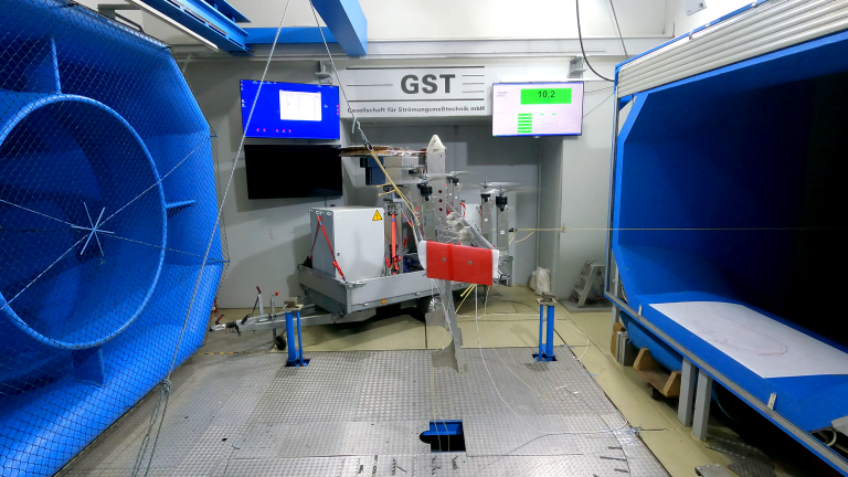
Various wind speeds were tested, starting at 0m/s and going up to 20m/s. In the picture above the wind speed is 10.2m/s, as indicated in the green box on the display in the upper right corner. The kite maintained stable hover flight at every wind speed. This means that the system in its then-configuration was already capable of undocking and docking to the ground station in high winds. Performance will improve further in the near future, when the results from the above described, first tests on the measurement shaft are incorporated into the control software of the kite.
Kitekraft system proves full control authority during hover in high winds.
The second batch of test runs focused on mapping the performance of different rotor configurations, shown in the image below. On the left, one of the CFRP rotors is shown which were optimized in-house. These rotors consist of different symmetrical airfoil cross-section and were optimized for the motoric as well as the generative mode.
On the right, one of the currently used, off-the-shelf injection molded rotors with two blades is shown. This rotor was also tested in stacked configurations, using two or three of these two-bladed rotors at the same time, resulting in a four- and respectively six-bladed setup.
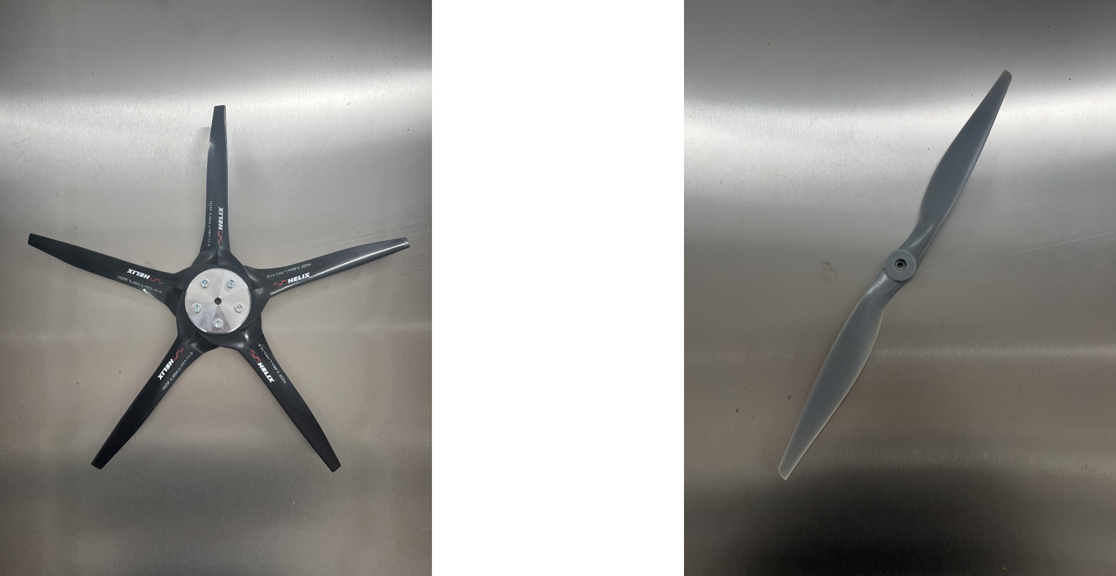
All rotors were tested at speeds of up to 8000RPMs (tip Mach Number of around 0.54) and various airspeeds. The CFRP rotors and the six-bladed configuration of the injection-molded rotors already generated the same thrust at lower rotational speeds, which is beneficial for noise reduction. While Kitekraft's systems will definitely be fitted with customized rotors in the near future, such a stacked configuration could be used as an economic shortcut for improving the performance and reducing the noise emissions of our current demonstrator immediately (see also: How to Develop Flying Wind Turbines Quickly and Cost-Efficiently?).
The efficiency of the in-house designed rotors is over 80% - a very good performance.
The efficiency of the CFRP rotors was measured with values of over 80%. This is a very good value and stands as proof to Kitekraft's in-house optimization algorithms, which will be of great value for the design of future system sizes.
To sum up, the conducted tests and findings made mark a significant milestone in the path to a rugged flying wind energy system. Firstly, it was demonstrated that the kite can hover stably for launching and landing in high winds. Secondly, it was shown that Kitekraft's newly optimized propellers performed efficiently.


